


|
|
|
(Click on a title to jump to the section) Kingsnorth - Original Design Specification Kingsnorth - The First Twenty Years
Firstly....the end
Kingsnorth Power Station was a dual-fired coal and oil fired power station on the Hoo Peninsula, Medway, Kent. The four-unit station, owned and operated by E.ON UK, had a generating capacity of 2,000 MW. She was capable of operating on coal, oil or both though in practice oil was used only as a secondary fuel or for startup. It was also capable of co firing biofuel, up to a maximum of 10% of the station's fuel mix. A replacement power station, also coal-fired, was once considered, but plans were abandoned. The proposed replacement attracted substantial public protests and criticism, including the 2008 ‘camp for climate action.. The station closed as a result of the EU's Large Combustion Plant Directive (LCPD), which requires stations that are not equipped with flue gas desulphurisation to close after 20,000 hours of operation from the 1st January 2008 or the end of 2015, which ever came first. Kingsnorth ceased generation on the 17th of December 2012 at 15:10 hrs, having consumed all its LCPD hours. A Once Proposed replacementAs a replacement for the four old Kingsnorth units, in October 2006 E.ON proposed the construction of two new coal-fired units, Kingsnorth Units 5 and 6. The proposed construction of two new 800 MW supercritical coal-fired power units on the site, was to be operational "as early as 2012". E.ON expected the supercritical units to reduce carbon dioxide emissions per unit of electricity by around 20%, as compared to the existing subcritical plant. E.ON also said the new units would be "capture ready" to allow the option of retrofitting with carbon capture and storage (CCS). Their environmental statement read: "CCS will be considered as an option...subject to the process of CCS being allowed by law and incentivised by a suitable framework and technological hurdles for the process being overcome” On 31 March 2008 E.ON announced that the new Kingsnorth power station would be used in a bid for the Government's carbon capture and storage competition. In addition E.ON proposed that the planning decision should be delayed until after the Government has completed its consultation on CCS. On 30 June 2008 it was announced that Kingsnorth project had proceeded to the next stage of the competition (prequalification) with three other competitors. In March 2009 Ed Miliband said that he was postponing a decision on Kingsnorth and then E.ON chief executive said that "Without commercial carbon capture, it's 'game over'" On 7 October 2009 E.ON postponed the replacement until at least 2016. On 20 October 2010 it was announced that the build of the replacement had been shelved.
Brief History Of The Electricity Supply Industry Electrical generation using steam…..where to start?…well… In 1698 Thomas Savery invented the very first steam driven engine, it was used to pump water from mines, in 1769 James Watt patented his much improved, more efficient and powerful version and soon replaced the Savery machines. In the year 1800 Count Alessandro Giuseppe Antonio Anastasio Volta discovered the electric cell using copper and zinc electrodes immersed in a solution, this led to the Voltaic Pile or battery as we now know it. Shortly after, Humphry Davy (he of the safety lamp fame) found that an arc light was produced when electricity from the Volta’s ‘battery’ was passed between two carbon pieces. In the 1820’s André-Marie Ampère took the credit for establishing a relationship between magnetism and wire carrying electricity from a battery. On the 20th November 1831 Michael Faraday demonstrated electromagnetic induction to the Royal Society and proved that electricity could be produced by moving a magnet through a coil of wire. The 1870’s saw the development of the armature, this led to the production of the first continuous electricity generating machines, driven by steam engines. From about 1875 arc lights were being used in public places such as theatres, shops and railway stations, in 1879 Joseph Swan invented the incandescent light bulb, some 10 months after Swan demonstrated his invention Thomas Edison also claimed he had invented it. In 1880, the world’s first public power station was opened in Godalming, unfortunately the publics enthusiasm for electricity was poor and the station was soon forced to close. 1882 saw the Holborn Viaduct station built by the Thomas Edison's Electric Light Company hand in hand with the Corporation of the City of London, this venture was more successful than Godalming and the trend for electric lights was set. In 1890, Deptford power station was completed and began to supply power to the central London distribution system, up until then consumers were supplied by local power stations each having their own ‘districts’, by 1903 London (not even the area of today's Greater London) had over seventy separate power stations. The 1909 Electric Lighting Act was passed in an attempt to encourage the growth of the electrical supply industry not only in London but in the rural areas too. The act gave rights for compulsory purchase of land for power station building and the right to dig up roads for laying supply cables. The intention was to encourage the building of bigger, more efficient stations and to create a wider supply network. Unfortunately there was no coordination and organisation between areas and the Electricity Supply Act of 1919 appointed Electricity Commissioners to the Dept of Transport who took over the responsibility for electrical affairs from the Dept of Trade. The act also authorised the establishment of Joint Electricity Authorities, these were able to co-ordinate within areas and assume control to standardise supply and improve generating plant efficiency. By 1921 there were 80 supply companies in Greater London operating between them 70 generating stations employing 50 separate systems of supply at 24 different voltages and 10 frequencies. In 1925 the Joint Electricity Authority was finally established and plans were made to set up a large scale, standardised network of supply lines that would be feed by larger, more efficient power stations. A Central Electricity Board was established, this body took on the task of expanding the network of supply lines to wherever there was demand, by 1933 a vast grid of supply lines was in place operating at 132kV. They would buy power from the most efficient generators and sell it to whichever authority who wanted it. The early 1930’s saw an increase in larger stations providing the new distribution system with a cheaper, more reliable supply of electricity. This, together with plant age issues caused a rapid reduction in the number of smaller generators. When the network was first set up the Authority had 162 selected stations, 21 of which ran continuously, another 440 other stations were also connected to the grid but closed down within a short time as they were not required. The drive for cheaper power was on and much bigger generating sets were planned and built, the number of smaller stations reduced rapidly as the more efficient machines were commissioned. Following the Electricity Act of 1947, the government decided to step in and take control, the intention was to take full control of both the generation and distribution systems. The new nationalised generating pool formed in 1948 was originally called the British Electricity Authority (BEA) but was soon renamed the Central Electricity Authority (CEA) to avoid confusion with the British European Airways. Less than a decade later, the government decided to reorganise and rename the whole setup, the Central Electricity Authority was replaced by the Central Electricity Generating Board (CEGB). New, bigger stations were planned to cater for the increasing demand. At the heart of the new setup was the central control room of the National Grid. The engineers who worked there had information about the running costs and availability of every power producing plant in England and Wales. Here they would constantly anticipate demand, monitor and instruct power stations to produce electricity, or stop producing electricity, by reference to what was known as the "merit order", based on the efficiency of a particular generating set. The objective was to ensure that a reliable, efficient supply to the nation was always achieved at the lowest possible cost. The CEGB had an extensive research and development section with its three principal laboratories at Leatherhead (Central Electricity Research Laboratory, CERL), Marchwood Engineering Laboratory (MEL) and Berkeley Nuclear Laboratories (BNL). There were also five regional facilities. The CEGB provided a secure and stable supply of electricity for almost 50 years, from its nationalisation in 1947 to privatisation in the 1990s. The CEGB planned the construction of three 1,800 MW coal-fired power stations in the period before privatisation. No application for consent was made for Kingsnorth 'B' and the application for Fawley 'B' in Hampshire was subsequently withdrawn. West Burton 'B' was granted consent in March 1990 but construction was never started. The Kingsnorth site was subject to extensive studies as to the suitability for building two 900MW coal fired units fitted with FGD. Plans for a new RORO jetty and heavy load berth capable of accepting 50,000ton ships were made as well as a new rail connection through to Higham junction to allow transport of imported coal to Didcot power station. Although electricity privatisation began in 1990, the CEGB continued to exist until The Central Electricity Generating Board (Dissolution) Order 2001, came into force on the 9th November 2001 Initially, after privatisation, the electricity market in the UK was built upon the break-up of the CEGB into three generating companies a distribution company, the National Grid Company. The three generating companies were Powergen, National Power and Nuclear Electric. The first two were privatised in the early 1990s and the latter was held in public ownership for several years before combining with Scottish Nuclear and privatised as British Energy. A proportion of the CEGB’s nuclear fleet, its older Magnox reactors, remained in public ownership as Magnox Electric, and was later combined with BNFL. After privatisation, consumers became reliant on a system that was becoming more and more fragmented by sell-offs, acquisitions and closures. Company profits and shareholders interests were foremost in the eyes of the owners of the electricity generating plant. Government based environmental targets and ceilings announced in the early 2000s will force companies to consider closure of some of their coal burning stations due to economic reasons. 1988 - Announcement to privatise the UK electricity industry. 1989 - Powergen announced as one of the new generating companies and signs up to sponsor a television program and the ITV weather. In December signs a deal to provide Toyota. 1990 – Dissolution of the CEGB and Powergen is launched as a PLC. 1991 – Government sells 60% of Powergen to the public. 1993 – Killingholme CCGT opened and Schkopau power station in Germany bought. 1995 – Remaining 40% of Powergen stake sold to the public, in November High Marnham and Drakelow power stations are sold. 1997 – Cottam Development Centre set up in partnership with Siemens. 1996 – Powergen puts in a bid to buy Midlands Electricity Board (MEB) but the government rejects it. 1998 – Powergen North Sea Ltd is sold and East Midlands Electricity (EME) bought. 1999 – Fiddlers Ferry and Ferrybridge power stations sold. Powergen start to sell electricity to the domestic market. 2000 – Louisiana Gas and Electric and 50% of Corby Power Ltd bought. Cottam power station sold. Launch of financial and telecommunications services. 2001 – E.ON AG makes moves to buy Powergen 2002 – E.ON AG buys Powergen, London Irish win the first ever RU Powergen cup. 2003 – Bradford Bulls win the first ever RL Powergen cup. Agreement reached for Powergen to buy MEB (ref 1996).Announcement made to close Drakelow and High Marnham power stations. 2004 – Newcastle Falcons win the RU cup. St Helens win the RL cup. Powergen buy MEB, link them with EME and are renamed Central Networks. Powergen itself is ‘rebranded’ as E.ON UK plc. 2005 – Leeds Tykes win the RL cup, Enfield CCGT bought by E.ON, Scroby sands offshore wind farm opened. 2005 - The EU's Emission Trading Scheme, set up to reduce CO2 emissions, signals the closure of coal fired power plant over the next 10 years. In the same year the Department of Transport released a report stating that the number of vehicles on the roads of Britain will increase by 40% by the year 2025. KINGSNORTH POWER STATION ORIGINAL DESIGN The script below was kindly provided by Eric Stather (Kingsnorth 1967 - 87), the text is 'as sent' apart from a font adjustment and the deletion of 'sensitive information'. Original Plant Design features as installed in 1967 Main Turbines The main turbines are of the five cylinder tandem compound design with steam inlet conditions of 538 degC and 2,300 p.s.i.g. with exhaust condition of 1.1 in Hg. Each turbine has a maximum continuous rating of 500 MW with an additional overload capacity of 26.5 MW for three, one-hour periods per day at a slightly reduced efficiency. The cylinder arrangement comprises a single flow High Pressure, a double flow Intermediate Pressure and three double flow Low Pressure cylinders. The three LP cylinders exhaust through six outlets into an under slung axial flow condenser. All cylinders are of double shell construction and the rotors are stiff and solidly coupled with a thrust bearing sited between HP and IP cylinders. Four HP throttle valves and four IP interceptor valves are mounted directly onto their respective cylinders. The HP rotor consists of a solid forged rotor with eight stages of continually shrouded vortex blading, Each flow of the double flow solid forged IP rotor has seven stages of similar blading. For development purposes some of the L.P. rotors were solid forged and others of welded construction ,each flow carries six stages of blading. Unique arch braced cover banding was used as shrouding and this obviates the need for lacing wires. The final stage blades at 37 inches long on a base diameter of 60 inches. Stellite erosion shields are fitted to the inlet edges of the moving blades of the last two stages of each L, P. flow. Steam is tapped off the main turbine for use in regenerative feed heaters and for driving the turbine driven steam feed pump, No. 7 HP heaters and the turbine driven feed pump are supplied with steam from the HP cylinder exhaust (cold reheat steam) at 592 p.s.i.g. Tapping points on the feed pump turbine supply bled steam to No's 6 and 5 HP. heaters. The exhaust steam from the feed pump turbine is taken to the IP/LP cross under pipe. Bled steam is tapped off the LP turbine before the second stage for the deaerator, before the 3rd stage for the No 3 direct contact heater, before the 4th stage for the No 2 direct contact heater and before the 5th stage for the No 1 direct contact heater. Feed Heating System and Feed Pumps Seven main stages of regenerative feed heating are provided. These comprise three separate direct contact low-pressure heaters, a deaerator, and two parallel lines each of three stages of high-pressure heaters. Each stage consisting of two head down indirect or non-contact heaters. These six H.P. heaters are arranged in two parallel banks to give a final feed temperature of 254°C. All H.P. heater drains are cascaded through flash boxes, the No. 5A and 5B heater drains being cascaded from flash boxes to either the deaerator or the main turbines condenser. Several earlier stages of condensate and feed heating are provided by the generator coolers and the gland steam vent condenser, Circulation of condensate and feed water through the various stages of feed heating is provided by three 50 per cent duty two-stage extraction pumps, two 100 per cent duty glandless deaerator lift pumps and one 100 per cent duty main turbine driven boiler feed pump with two 50 per cent duty starting and standby electrically driven boiler feed pumps. Surge and make up capacity is provided on a station basis by two 1, 500,000 gallon reserve feed water tanks. The feed pumps take their suctions from the deaerator and discharge directly through the H.P. heaters into the boiler feed lines. The pumps are tandem units with a slow speed suction stage and a separate high-speed pressure stage coupled through an epicyclical gearbox. Each unit has an automatic microwire suction strainer supplemented by a magnetic filter section to remove any particles which may pass the microwire 0.008 inch mesh. The main feed pump turbine oil system and gland steam system are integrated with those of the main turbine. The suction stage pump is a single stage horizontal spindle type, driven at 2,850 r.p.m. via a reduction gearbox. The pressure stage pump is a four-stage unit with floating metallic ring glands, directly coupled to the feed pump turbine and driven at 4,150 r.p.m. The main pump is designed to deliver 3,905,000lb/hr at 2,900 p.s.i.g. The turbine is rated at 16,970 b.h.p. with inlet steam condition of 592 p.s.i.g, and 343°C and steam flow of 423,580 lb/hr and thus cannot meet boiler feed demand until the unit is at 50 per cent of its maximum continuous rating, that is 250 megawatts. Starting and standby pumps are of similar design to the main feed pumps but are driven by 9,000 b.h.p. motors with the suction stage directly driven by the motor at 980 r.p.m. and the pressure stage pumps through the epicyclical gearbox at 5,500 r.p.m. The drive motors are 11 kV slip-ring induction motors with a liquid resistor speed control device giving speed variation down to 70 per cent of full load speed. Condensers The condensers adopted are of the under slung single shell, single pass axial type. The condenser runs the whole length of the L.P. turbine with four separate single passes, two at the top and two at the bottom, circulating water passing through each in opposite directions. Each pass has its own water box and compensating bellows. The tubes were 1 inch in diameter and 60 feet long of 70/30 aluminium brass, and expanded into double tube plates at each end. Fifteen sagging plates were provided along the length of the span. 17, 336 1-inch diameter tubes were installed with an additional 1,710 1.125 inch diameter tubes in the air-cooling section. Three 50 per cent duty Nash Hytor air extraction pumps are provided with an additional quick start exhauster. Main Generators Each 3,000 r.p.m. two-pole generator is rated at 500 Megawatt a power factor of 0.85, but may provide a continuous over-load output of 526.5 MW with increased hydrogen pressure. The rotor and stator cores are cooled by hydrogen at a normal pressure of 60 p.s.i.g. with the stator windings water-cooled. Excitation is supplied from a self-excited, pilot alternator and a main exciter-alternator with a solid-state rectifier. The voltage of the generator output is 23.5 kV, this is passed to a 600 MVA transformer which steps up the voltage to 400 kV for direct connection, through high voltage circuit breakers, to the grid system. Circulating Water System Water for cooling the turbine condensers is drawn from the River Medway, it enters the station through two 11 ft 3 in square concrete pressure culverts. These are screened by double-entry rotary drum screens to retain any large particles of foreign matter. Four concrete volute cooling water pumps impel water to the units cooling systems. All water extracted from the river is returned via two culverts of similar size to the inlets passing over a stone weir to Damhead Creek. The whole system is approximately two miles in length. The discharge culverts have vacuum-breaking valves to cushion any surges caused in the event of an emergency shutdown of the cooling water pumps. Two auxiliary pumps are provided for dewatering the inlet culvert and give auxiliary cooling services when the main units are shut down. All ferrous-based plant in contact with seawater and the unloading jetty structures is provided with cathodic protection to combat seawater corrosion. International Combustion Ltd Dual Fired Main Boiler Each boiler house is 370 feet long, 165 feet: wide and 234 feet high, and houses two water-tube boilers of the divided furnace, assisted circulation, type. Each boiler is capable of producing 3,550,000 lb of steam per hour at 2,400 p.s.i.g. and 541 deg C at the superheated outlet, with reheat of 2,900,000 lb per hour from 348 to 541 deg C and 590 psig at the reheater outlet, based on a final feed temperature at the economiser inlet of 254 degC. In order to take advantage of the price and availability of coal and oil in the 1960s, each furnace (which is of fully welded membrane wall construction) was designed to operate on either fuel with a (maximum continuous rating) efficiency on coal of 90 per cent and 89 per cent on oil. For the original oil firing mode, heavy fuel oil with a viscosity of up to Redwood No. 1 6,000 sec was fed into the furnace by 48 burners arranged at the eight corners in vertical banks of six, the bottom bank being arranged in two groups for use in light up. The pulverised fuel burners are interspersed with the three lower banks of oil burners. Seven stages of superheater and two stages of reheater are provided and as the final steam temperatures are only 541 deg C, Austenitic steels are not used. Two all-welded, continuous loop, transverse finned tube economisers are arranged end to end to operate in parallel. Two Howden regenerative air heaters are provided together with two bled steam air heaters located between the forced draught fans and the main air heaters. These bled steam air heaters were to be used for cold start-up and when firing oil. Two 1,180 hp Forced Draught fans are installed and two 1,565 hp Induced Draught fans are installed, the latter drawing gasses from three Davidson “R” type straight flow mechanical dust collectors via three Sturtevant parallel plate electrostatic precipitators. For coal firing, five International Combustion Lopulco Pressure Mills supply pulverised coal to the furnace, each mill feeding a horizontal ring of eight tilting burners arranged for tangential firing configuration from each corner of the divided furnace. The arrangement, coupled with a 15-inch gap at either side of the division wall, is designed to balance the combustion conditions in each furnace. Ash and Dust Handling Ash collects at the bottom of the boilers when in the coal burn regime and is removed after quenching by water sluices. Two crushers were fitted on each boiler reduce any large ash to a manageable slurry. Dust and grit from the precipitators that cleanse the flue gases is collected in either a wet or dry state and is either discharged to dust hoppers for resale or pumped out as slurry to lagoons on the east side of the station. Water Treatment Water of high purity is required for use in high pressure boilers. This calls for a demineralisation plant of several processes capable of handling one million gallons a day. The water is passed through a Cation unit, where the salts are converted into their corresponding acids and then through a scrubber tower for carbon dioxide removal. After passage through the Anion unit for acid removal and neutralisation, the water is further "polished" in one of the three mixed-bed units to render it suitable for "make-up" for the feed water systems. Gas turbines Four 22.4 mw English Electric Gas Turbine Generators were provided housed in a separate sound proof building. Each powered by two distillate fuelled Rolls Royce 1533 Avon Gas Turbines. The expansion turbines are directly coupled to 28 MVA air-cooled alternators. The alternators supply the 11 kV unit boards direct and each gas turbine provided with an 11 kV/415V transformer to power auxiliaries. The gas turbine auxiliaries can also be supplied by a 62.5 kVA standby diesel driven alternator set, This enables the station to be started when completely disconnected from the grid system. The gas turbines, which are equipped with automatic synchronising facilities, can be selected to start up automatically if the grid system falls below 49.7 Hz. Auxiliary boilers Two auxiliary boilers capable of producing 45,000 lb per hour of steam at 400 p.s.i.g. at 260 deg C provide soot blowing steam for the main boilers during periods of light load, feed-water deaeration, main boiler steam airheaters, fuel oil heaters, oil storage tank heating, and heating the auxiliary buildings. Station Electrical supplies Electrical auxiliary supplies are provided by a three voltage system: two 11 kV station boards supplied by the 132 kV substation via two 50 MVA transformers, and four 11 kV unit boards. The latter can be supplied either from the 30 MVA unit transformers, the 22,4 MW gas turbine, or from the station board inter-connectors. The feed pumps and circulating water pump motors are supplied from the 11 kV boards. A comprehensive system of auxiliary power supply includes a safe supplies system for the instrumentation and control equipment, Station Switchgear and Transformer Details 11 kV switchgear Type of circuit breaker Air break Breaking capacity 750 MVA Current rating 2,000 amps 3.3 kV switchgear Type of circuit breaker Air break Breaking capacity 150 MVA 415 volt switchgear Type of circuit breaker Air break Breaking capacity 31 MVA Transformers There are approximately 115 electrical transformers within the power station ranging in size from 1.0 MVA to 660 MVA Electrical power transmission Kingsnorth Power station supplies the national grid system which interconnects other power stations power stations and load centres. The electrical power is generated at 23,500 volts and, for reasons of economy, is transmitted in the national grid at much higher voltages. The generators feed transformers which change the voltage to 400,000 volts and are in turn connected to bus-bars by means of switches which control the power. The bus-bars are a means of collecting the output from each generator allowing it to be distributed through various transmission lines carried by pylons across the country. Other transformers on site which the voltage from 400,000 to 132,000 volts and feed a further system of bus-bars to which connect via underground cable circuits to supply power to the Medway towns. Both the 400,000 volt and 132,000 volt bus-bars and switches are in covered accommodation at Kingsnorth to prevent airborne pollution of the insulators affecting their electrical efficiency. For the 400,000 volt switchgear, this has meant enclosing an area 700 feet by 440 feet to a height of 75 feet, (an air-space of 23,100,000 cubic feet). Technical details Civil Engineering Site area 400 acres (162 hectares) Turbine hall 954 ft x 135 ft; height 110 ft (290.7 m x 41.2m; height 33.5m) Boiler house each 370 ft x 165 ft; height 234 ft (112.7 m x 50.3m height 71.3m) Auxiliary Gas Turbine House 180 ft x 90 ft; height 48 ft (55.4 m x 27.7m; height 14.8 m) 400 kV substation 700 ft x 434 ft; height 70 ft (213.3m x132.2 m; height 21.3m) 132 kV substation 296 ft x 82 ft; height 50 ft (90.2 m x 25 m; height 15.3 m) Chimney 4 x 23 ft dia (4x7 m dia) flues Height 650 ft (198m) Windshield dia. at base: 86 ft (26.2m) Windshield dia. at top: 64.7 ft (19.7m) Circulating water pump house 200 ft x 126 ft; height 32 ft (60.9 m x 38.4m; height 9.8m) Plant and Equipment Main boilers Assisted circulation, single drum, Divided furnace Maximum continuous rating 3,550,000 lbs / hr (1,610,250 kg / hr) Superheater outlet pressure 2,400 p.s.i.g. (166 bar) Superheater outlet: temperature 541 deg C Reheater steam flow 2,900,000 lbs / hr (1,315,418 kg / hr) Reheater outlet pressure 590 p.s.i.g. (40.7 bar) Reheater inlet temperature 348 deg C Reheater outlet temperature 541 deg C Economiser water inlet temperature 254 degC Drum pressure 2,590 p.s.i.g. (178 bar) Main Turbines Type Tandem compound design. No of cylinders Five: 1x single flow High Pressure 1x double flow Intermediate Pressure 3x double flow Low Pressure Speed 3,000 r.p.m. Turbine heat rate 7,540 BThU / Kwh (7,955 J / Kwh) Steam pressure at ESV. 2,300 p.s.i.g. (159.6 bar) Steam Flow at ESV. 3,500,000 lbs / hr. Steam temperature at ESV. 538 deg C Steam pressure at IV. 590 p.s.i.g (40.0 bar). Steam Flow at IV. 2,900,000 lbs / hr. Steam temperature at IV. 538 deg C Main Generators Maximum continuous rating 500 MW at 0.85 power factor Speed 3,000 r.p.m. No of Phases Three Output Frequency 50 Hz. Stator voltage 23.5 kV Stator cooling medium Water and Hydrogen Rotor cooling medium Hydrogen at 60 p.s.i.g. (4.1 bar) No of Poles Two Exciters AC. Pilot with AC / DC. solid state rectifier Main exciter output 2,940 amps 520 volts D.C. Condensers Type Under-slung axial flow with four single passes Condenser back pressure 1.1 in Hg abs. Number of tubes 19,046 Length of tubes 60 ft (18.3 mtr) Feed heating plant Number of L.P. heaters Four, including a deaerator Type Direct Contact Number of HP heaters Six ( two banks of three) Final feed temperature 254°C Main Feed Pumps Main feed pump flow 3,905,000 lbs / hr (1,403,482 kg / hr) Feed pressure 2,900 p.s.i.g. (200 bar) Number One per unit steam turbine driven Steam turbine GEC Erith Rating 16,970 b.h.p. Inlet Steam pressure 512 psig Inlet steam temperature 343 deg C Steam flow 423,580 lbs/hr Pumps Sultzer Type Two stage Suction stage Single stage horizontal spindle type Speed 2,850 R.P.M. Pressure stage Four stage unit Speed 4,150 R.P.M. Reduction Gearbox Epicyclical Gear Ratio 1.0 / 1.45 Flow 3,905.000 lb/hr (1,403482 kg / hr) Discharge Pressure 2,900 psig Starting and standby feed pumps Flow 1 ,952,500 lbs / hr (430,066 kg / h r) Type of drive 11 kV variable speed motor Design rating 9,000 bhp Maximum motor speed 980 r.p.m. Maximum pump speed 5,550 r.p.m. Gas turbo-generators Number Four Rated output 22.4 MW Gas turbine engines Rolls Royce 1533 Avon Type of fuel Gas Oil Generated voltage 11 kV Auxiliary boilers Number Two Rating 45,000 lbs / h r (20,430 kg / h r) Working pressure 400 p.s.i.g. (27.6 bar) Final steam temperature 260°C Fire protection equipment Water spray pumps Diesel driven, centrifugal, auto start Number Four Capacity 2,100 gpm. (1,591 Itr / sec) Discharge head 293 ft head (89.31 mtr head) Hydrant pumps Two diesel driven and one electric, centrifugal Capacity 1,680 gpm. (1,273 ltr / sec) Discharge head 301 ft head (91.74 mtr head) Electrical plant 400 kV Plant Generator transformers Ratio 23/400 kV Rating 600 MVA Super grid transformers Ratio 400/132 kV Rating 240 MVA Switchgear Rupturing capacity 35,000 MVA Busbar rating 4,OOO amps Overhead Rating 1,800 MVA per circuit 132 kV Plant Switchgear Rupturing capacity3,500 MVA Busbar rating 2,000 amps Underground cables Rating 120 MVA
Kingsnorth Power Station, The First Twenty Years
The script below was kindly provided by Eric Stather (Kingsnorth 1967 - 87), the text is 'as sent' apart from a font adjustment and has been approved as 'insensitive information'.
“The First 20 years of Operation” “Historical recollections and significant events.”
Kingsnorth Power Station in Kent is one of ten 2,000 megawatt plants constructed during the 1960s by the Central Electricity Generating Board, part of the then UKs Nationalised Electricity Supply Industry. It stands on a site of 162 hectares (400 acres) of reclaimed marshland on the Hoo Peninsula and on the northern bank of the tidal estuary of the River Medway, close to the village of Hoo St. Werburgh. The historic towns of Rochester and Chatham are a few miles upstream. The marshy land around this area has history extending back into the mists of time. Dykes probably started by the Romans protect the surrounding low-lying land. A Roman burial urn and a cache of Bronze were uncovered close to the power station site. In the two world wars the River Medway was a centre of naval activity with the Royal Naval Dockyard then situated at Chatham. Kingsnorth's association with the Royal Navy stems from a light railway system that ran across the adjacent, now industrial site, transporting munitions off loaded from warships before they entered the dockyard at Chatham. In 1913 the Royal Navy constructed an Airship Station close to the power station site. The foundations of an airship hanger are in the area adjacent the power station car park upon which the heavy stores building stands. The original power station design was based on a dual-fired boiler concept with the capability of burning 100% coal or 100% oil or in various combinations of both fuels (unique at that time in England and Wales). This feature was intended to take full advantage of the varying availability and cost of both these fuels at the time. Kingsnorth Power Station was the first of a series of this type under consideration by the CEGB no further power stations of this design were however constructed. Four five-cylinder 500-megawatt hydrogen and water-cooled turbo-generators were installed operating on a high pressure and temperature reheat steam cycle. In addition, four 22.4 megawatt gas turbine driven generators were installed as standby emergency supplies for the main generators in case of loss of the normal station supplies. Gas turbine generators were used extensively for "peak lopping" throughout the UK in the 1960-70s to supplement the UKs main generating plant. The location for the power station was chosen for its nearness to the major load centre of London, together with the plentiful supply of water available from the River Medway that removed any need for cooling towers. The land, though marshy, could be reclaimed for power station construction. An additional and significant advantage was the facility for deep water berthing in the river. Because of this ability to berth large oil tankers, and colliers, Kingsnorth was used as a fuel storage and transfer depot for other CEGB power stations in the south east of the country well into the late 1970s. The power station site 2013ed considerable problems in design and construction due to the high water table (the site is 1.2 metres below the highest tide level). The land having poor load-bearing qualities required extensive piling with various types needed to reinforce it, as also did the river frontage and circulating water pump house and its intake. Damhead Creek in the north east corner of the site originally extended into a marsh known as Damhead Fleet, over which the main power station building now stands. What was initially seen as a construction problem later however was seen as an advantage. The discharge for the very large quantities of cooling water needed to be taken from the River Medway was routed into Damhead Creek. Flowing back into the river, one and a half miles downstream from the cooling water intakes after use prevented re-circulation back to the main plant cooling system intake. The economic and technical considerations of building the station took into consideration the effect on the local amenities, and the ecology and natural characteristics of the area, endeavouring to strike a balance between the operational and environmental considerations. The need for conservation and the avoidance of pollution is seldom compatible with the efficient and economic design for large power plants and these factors 2013ed a difficult task to reconcile in the design phase. The large building structures were architecturally designed to blend in with the surrounding countryside by the careful selection of colour and texture of materials, together with a high multi-flue chimney to disperse the effluent gasses from the boiler plant well up into the atmosphere. Work commenced on the site in March of 1963 with the first power generated onto the National Grid in 1967. The station reached a full output potential in February 1973. Mr.Eric Varley the then Secretary of State for Energy officially opened Kingsnorth Power Station on 18th. April 1975 with many important dignitaries in attendance. In the weeks leading up to this event various plant failures had caused progressive shutdown of the main units and the day before the opening only one remained on load. This unit was then lost with an economiser tube leak the afternoon before the ceremony, which then took place with total plant silenced. (This is the offending tube)
The offending tube having been hurriedly removed was 2013ed to the gathered visitors with due ceremony by Mr. Ron Horder the Station Manager. One of the very early operations carried out was the commissioning and test trials on three of the four main steam turbines, which had been completed before their boilers. These tests were achieved after a boiler salvaged from the decommissioning of the passenger liner “The Queen of Bermuda” was installed in a temporary building and coupled into the stations auxiliary boiler range to supplement the output of the two auxiliary boilers. The No.1 turbo-generator was first synchronised onto the national grid system using this source of steam and generated a small output for a short time. In the early operational phase of the station a number of major faults and problems were encountered from plant, control systems and associated equipment. Some arose from poor specification of materials used in the installation, and others from inadequate design features. Extensive testing and modifications were necessary to identify the unreliability sources that existed. The design arrangements of the casing supports and the bearing pedestals is unusual on these turbines and determines the way in which expansions influence other parts of the machine. Early operational experience identified a number of restrictions on these casings due to inadequate lubrication from the casing sliding feet automatic greasing feature. A major problem highlighted during tests on the first turbine to be under steam was in the way the HP rotor outboard bearing pedestal behaved during run-up and loading. This 2013ed problems by its failure to move correctly as the multi-rotor turbine expanded. This unusually tall pedestal designed to slide horizontally tilted over due to the load from the HP Casing, and the friction of its sliding foot arrangement. This caused a number of failures of the rotor bearing, and the various oil sealing mechanisms 2013ing a constant fire hazard. Failure of the turbines over-speed on load test facility also resulted from this phenomenon, making it necessary to carry out regular off load actual overspeed tests to prove the integrity of this particular safety device. To over-speed the turbine above the normal speed of 3,000 r.p.m. carried the possible risk of ejection of the low-pressure turbines final blade arch cover bands giving rise to condenser tube damage and contamination of the feed water systems that would then result. Wear on the main speed governor drive bearings also took place from this bearing pedestal malfunction causing the need to shutdown with loss of station generation. Modifications were carried out following further extensive testing to alleviate the cause removing further operational restrictions. On load testing of the steam valve hydraulic systems was also a problem, with risk of the IP Turbine Reheat Interceptor Valves failing to reopen after closure. It was then necessary drop load reducing the steam pressure across the valve to facilitate reopening. Thermal distortion of the HP casings was always a concern particularly if a heat soaked turbine was held at speed for any length of time such as after a loss from full load. It was necessary to monitor the HP turbine casing outlet steam conditions to avoid saturation temperatures being reached. Failure to understand the effect of this condition resulted in casing distortion and severe rotor damage on No 3 HP turbine in 1976 when holding the turbine at speed during a difficulty to restore it after loss from full load. To identify the full extent of these turbine design problems the No1 turbine was used as a test bed and fitted with a large number of measuring devices. The No1 Bearing Pedestal was monitored during run up and loading using a calibrated inclinometer and with air gauges attached to all casing gland housings to measure the rotor clearances and alignment together with expansion and strain gauges attached to all casing sliding feet mountings. All the measured data was continually transferred to a data logging display, allowing observation as the expansions took place. From the data obtained design modifications were determined to eliminate these pinch points and remove initial operational constraints. LP rotor final blade, arch cover bands and erosion shield ejection, was a regular danger during run-up and overspeed tests, and was a constraint in the early years. Regular on load inspection was necessary using an introscope device that enabled inspection of these items whilst on load. Complete redesign of the blades and their circumferential strengthening features was later carried out to remove this hazard. Regular failures of turbine blade arch cover bands and erosion shields meant the turbine had to be shut down to remove the turbine outer casings and to replace the lost item. The overall time to achieve this repair was extensive with a fully heat soaked machine. A successful operational procedure was devised which allowed the turbine to be slowly unloaded and the steam temperatures reduced to achieve near start-up thermal conditions on desynchronisation with a significant reduction in downtime being achieved. Other problems on the turbine plant concerned the possible ingress of water from the Direct Contact Heaters into the turbines bled steam tapping points, which had potential catastrophic implications. This had occurred at another power station having this design of heaters. Additional quick acting non-return valves were incorporated on the bled steam pipework to overcome this after finding the closure action of the original valves suspect by often failing to close during on load tests or failing to reopen if successfully closed. Steam leakage from the HP Heater drains pipework flanges was a constant problem and on load leak-sealing techniques were adopted to reduce losses and maintain output. Early operation on the first unit exposed design problems with the main generators conductor insulation with stator electrical faults resulting. All generator windings were replaced as soon as possible after generators were commissioned. An additional generator stator was purchased to facilitate this and an on site programme to replace conductors on the other generators was instituted whilst not holding up commissioning programmes or excessive loss of output.
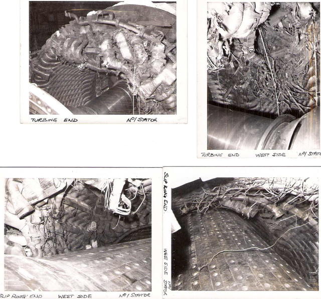
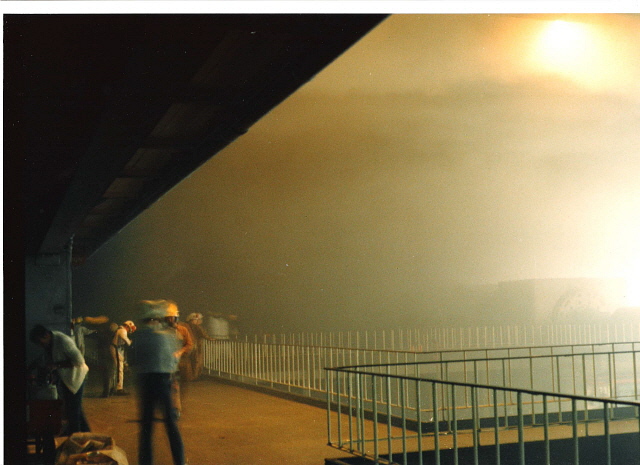
The design of the sealing arrangement on the generator electrical rotors for retention of the hydrogen cooling gas within the pressure casing was a major problem, with hydrogen escape and fire risk always a possibility. Stability of the automatic features to maintain oil pressure to the seals was ineffective and hydrogen loss always a potential hazard. Regular testing was carried out to ensure no unsafe hydrogen levels existed in the area. A comprehensive redesign of the sealing arrangement was later carried out to remove this problem. Moisture levels in the hydrogen cooling gas due to leakage from the stator winding cooling circuitry on required constant monitoring to ensure no detrimental effects to the insulation. On the main boilers the use of high-grade austenitic steels for the high temperature zones was not possible due to the degradation effect of burning heavy fuel oil in quantity. This lowered the final outlet steam temperature conditions reducing the boiler overall thermal efficiency. Major failures of the oil burners resulted from their non-retractable design due to end cap overheating and burner tip coking when in the re-circulating mode. Fouling of the boiler rotary air heaters on 100% oil burn was a regular feature requiring either on load or off load high-pressure washing to remove the build-up on the elements. Deterioration of the cold end plates was also a problem and frequent shutdown was needed to allow blanking of the gas passes to allow part load operation during the replacement work. The draught loss on the mechanical dust collectors proved excessive on 100% oil firing and removal was necessary to meet the capacity of the ID fans. These fans were subsequently upgraded to increase flow enabling the losses to be overcome Condenser problems arose early in the station’s life with tube erosion failures with mussel ingress from beds adjacent the CW Intakes. To alleviate this plugs where inserted at the inlet tube plate expansions to reduce the tube diameter at that point, retaining the larger mussels whilst allowing smaller ones to pass through the tubes unrestricted. Regular overnight part load internal cleaning of the inlet tube plates was carried out to maintain thermal efficiency. Condenser tube material specification was found to be incorrect for the estuarine water quality and tube leakage resulted. Re-tubing was progressively carried out using higher-grade material together with a revision of the internal steam flow paths to reduce air blanketing and improve air extraction efficiency. The main steam turbine driven feed pumps were initially unreliable with high wear in the gearboxes and steam valves closure problems. Blockage of the micro wire strainers due to fouling from debris entrainment from the direct contact feed system was also a problem. Gas Turbine start-up capability in the early operational phase was a major problem due to controlled run up sequencing features failing to follow the start interlocks. Start-up was often attained by manual intervention with matchsticks regularly used to hold in relays operated by hand as each item of the start-up sequence was completed. Both this problem and the regular failure of the gas turbine inlet compressor blading, requiring engine replacement resulted in the soundproofing hoods being permanently removed and the noise level substantially increased within the Gas turbine House. The fire protection for the engines was ineffective in this situation. From September 1968 when the first main unit was synchronised onto the National Grid and throughout the coal miners strikes of 1972 and 1973 and up until 1976 the station operated solely on heavy fuel oil, many of the coal burning and handling facilities being only partially completed and those that had been were not operational. In 1975 following crisis in the Middle East the cost of fuel oil rose significantly and a crash programme was instituted to refurbish and complete the coal burning installation. By late January 1976 the first unit was operating on an 80% coal 20% oil regime at 490 Megawatt, only 10 Megawatt short of its full output. Other units followed as plant and modifications were completed. Again during this period further design philosophy flaws were encountered particularly associated with the dual firing concept and extensive work was needed on the sequence control and boiler interlock features together with modifications to the pulverised fuel pipework and burners to achieve safe and reliable operation. Retraining of all operational staff was undertaken at the Fiddlers Ferry Power Station and the Leeds Unit Simulator School was progressively carried out with on site hands on experience to gain familiarisation with the different characteristics of burning the dual fuels. Operational and maintenance procedures were revised as this experience was gained. Firing coal identified an unusual problem in relation to the boilers heated down-comer tubes in which reverse flow was found to take place. Flow starvation occasionally took place as steam bubbles formed. This was associated with low drum levels following on from the introduction of further coal burners. The swelling of the water contents with additional heat release causing the drum level feed controls to restrict water flow into the boiler then having an inherent delay to recover the drum level on boiler pressure increase. Tests were initiated to obtain data, which enabled improved in drum level control to be installed. The boiler overall automatic controls proved very unreliable with most of the boiler operating under manual control during these early years. The installed flame stability and flame failure indication equipment was seen to be unreliable on coal burn and temporary equipment was manufactured on site to give operator confidence whilst replacement units were designed from test data obtained. The oil burners not in use and on burner tip re-circulation suffered from severe coking and required regular cleaning. Reinstallation of the burner then had to be rapid with the oil flow quickly restored to prevent burner cap overheating. Tube failures in the economiser and superheater zones were a regular loss of output. Coal import in quantity was a major problem with the Long Reach Jetty Cranes proving to be unreliable and inadequate for the purpose. To overcome these restrictions and as a temporary measure, mothballed cranes from the Northfleet Power Station were refurbished and transported bodily to site by a large floating crane. These, although more reliable still lacked the required necessary unloading capability and a self-unloading vessel the MV Telness designed for transporting bulk grain was contracted to add capacity. Ultimately a more robust crane, a boom bulk unloader and a Siwertell high capacity screw driven unloader, the latter an unusual machine in power station use, replaced these temporary items. Coal was sourced on world markets, stockpiled on the continent then transhipped to Kingsnorth as required. Contamination of these coals with concrete, rock and other debris was significant causing damage to the conveyors and the trash removal screens. The foreign debris that passed the damaged screening then caused jamming in the roller mills and required frequent shutdown of these plants remove the material and prevent damage. The burning of these coals brought further difficulty with heavy hard glass like slag forming in the boiler’s bottom ash boxes requiring quite unusual methods of removal. The frequent sound of large explosions could be heard as “Blaster Bates” blew the slag apart for manual removal. The rise in fuel oil costs in the late 1970s was not the only problem faced. The national demand for electricity did not rise as predicted and more capacity was on the national grid system than was required. It was necessary therefore to shutdown, or run plant at partial load to keep the electricity system stable. The large new power plant replacing the older stations on the system and now reaching the end of their operational life were found to be inflexible and unable to meet the demands placed on them. Plant needed to be shut down at night as the demand fell and restarted the following morning as it picked up once more. This operation known as “two shifting“, needs the surety of the plant achieving full output in a short timescale. The large 500 Megawatt units did not meet this capability and were running in uneconomical and inefficient part load conditions. In 1978 Kingsnorth became the first of these new large UK power stations to achieve any measure of success at operating in the two-shift mode. This was achieved after many plant modifications and revisions of operating procedures together with the determination by the stations operations staff to develop manageable techniques suitable for the units using either fuel to achieve the required flexibility. Between April and December 1978 a total of 369 two-shift operations of the large units on the grid system were recorded as being successful. Of these 200 were credited to Kingsnorth. The savings to the industry achieved by Kingsnorth Power Station alone was £400,000. In addition the station pioneered the two-shift operation of two units simultaneously with 29 of these carried out, saving £4,000 for each such operation. This was recorded nationally as a remarkable achievement. In the years covered here a number of incidents occurred on the site causing loss of generation. Some resulted from design features which contributed to plant failure, some from control sequence faults and others from human error. A number of these incidents resulted in major damage to installed plant some accompanied by severe fires which had catastrophic potential if not properly managed. The conduct of staff on duty taking preventative action to protect plant from damage whilst maintaining generation at times involving personal risk and in potentially dangerous circumstances was exemplary, often limiting damage and heavy repair costs. A major failure of one main circulating water pump inlet “butterfly” valve due to over rotation during commissioning activities flooded the entire underground pump house up to river level causing severe damage. This resulted from intercellular bulkhead doors being left open and cable access points not sealed during construction.
Damage to the generator hydrogen seals from very microscopic debris in the seal oil system was a problem and extremely fine canister filters had to be installed after the normal micro wire rotary strainers to remove this detritus. Hydrogen loss from the seals as a result of this damage required regular monitoring of the gas levels around the seal areas to be carried out. The unreliability of the generator stator windings insulation, which necessitated total rewind of all stators, was expensive but necessary. A stator electrical fault on Generator 2 released a large quantity of hydrogen gas into the turbine hall fortunately without any damage or major fire. The high voltage Generator Transformer winding insulation degradation was another problem and regular oil treatment, on load, was carried out to determine the extent of this deterioration. A rolling exchange and repair programme was instituted to carry out repairs and modifications. A number of fires on turbine and boiler plant took place either the result of oil pipework failure or poor contract maintenance that required costly outage periods to repair.
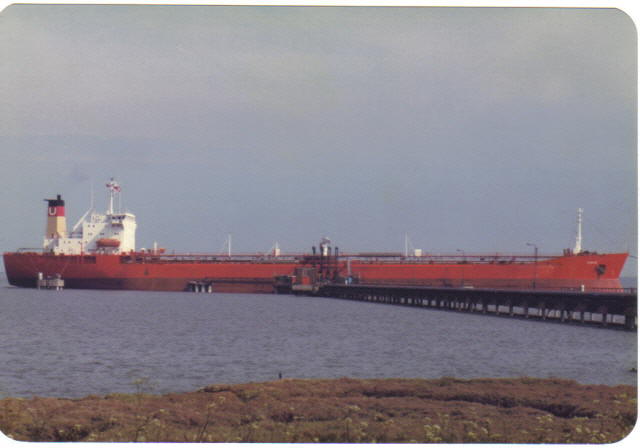
During commission tests on one main fuel oil storage tank filled with water, the tank was drained with the air release valve isolated causing the tank to implode. When commissioning of an additional 400 KV circuit breaker for the DC Link then in operation and teed onto the No.3 Unit’s 400KV circuit, a failure to observe the correct phase relationship across a newly installed circuit breaker with that of the system resulted in the synchronisation of the generator 180 degrees out of phase, extensively damaging the generator, the turbine, and the generator transformer. Accidents to personnel have occurred over the twenty years reviewed. Fortunately few were major. Early in the construction phase the chimney lift based on the design used in the NASA Apollo programmes failed and caused severe injury to the contractors personnel inside the cage. One operations member of staff suffered burns in taking action to safeguard plant during a major oil fire on No.4 turbine. Most distressing however was the fatality of a young mechanical fitter carrying out modification to a main turbine low-pressure cylinder. Kingsnorth Power Station plant in these early years 2013ed a constant challenge in its operation and maintenance and the successes achieved relied heavily on the calibre the workforce. In March 1984 the miners strike, which did not end until 1985, brought about another challenge to the station. Having successfully carried out modifications to achieve maximum coal burn a complete about turn was then made when it was required to restore maximum oil burn capability. Much of the oil firing equipment had been removed and this had to be quickly reinstalled with components refurbished and upgraded to help preserve the coal stocks other southeastern power stations not capable of heavy oil burn. Kingsnorth interconnected to the Grain Power Station by pipeline became the sole supplier of fuel to this station, as well as consuming large quantities of fuel oil itself. Miner’s pickets were unable to prevent sea-going vessels coming up the River Medway to constantly re-supply the power stations, although they did try but unsuccessfully.
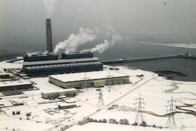
By concentrated effort both stations were kept at high loads throughout this difficult period. An unusual event took place when a bulk oil tanker berthed and was then seized by port authorities for outstanding payments. Under maritime law it was then not allowed then to be removed from the unloading berth, despite the prevailing circumstances, and prevented other vessels from unloading. This happened on a Friday afternoon. The vessel could only be legally moved from the berth by a High Court Judge’s authorisation which it being a weekend could not be obtained until the following Monday. By the time the necessary authorisation had been obtained and the vessel moved the fuel oil stocks were in great danger of running out with both stations facing possible load reduction or worse shutdown when needed most. Had this occurred the effect on the Grid system might have been dramatic at the worst time in the history of the Electrical Supply industry. Heavy snow and the following thaw in January of 1987 caused damage to power lines and insulators, many areas of the country were without electricity and power stations throughout the southeast experienced problems maintaining a stable supply, many staff were 'marooned' at Kingsnorth, supplies of food, bedding and 'essential clothing' were brought in by helicopter and Army vehicles. 15th October 1987 winds of up to 108 mph were battered the southeast damaging power lines so severely that Kent and most of Sussex were disconnected from the National grid. All Units at Kingsnorth tripped and the station lost all external electricity supplies. Restoration of power for the station was achieved by starting a small diesel generator which in turn supplied power to start a gas turbine. The gas turbine then provided electricity to power the main plant, this is a technique known as “black start”, tested in simulation but never in real situations, it proved successful.
The next major event faced was the Privatisation of the Industry announced in 1988 with the industry split up, the conventional power stations forming the PowerGen and National Power companies. Kingsnorth became part of PowerGen officially in March 1990 the CEGB ceasing to exist on that date. The changes in power generation that have followed Privatisation together with release of natural gas, previously classed as a noble fuel and denied in quantity for electricity generation. Together with those that followed from the entry into power generation of others companies, together with the requirements of the Kyoto agreement on emission reduction has 2013ed further obstacles to be overcome. Plant improvements have been carried out to meet a more demanding operating regime in this new environment. The future will no doubt be as unpredictable and met with the same determination as in the past. NON OPERATIONAL BUT NOTABLE ITEMS During the repainting of the main chimney capping in 1978, the year of the Queen’s Silver Jubilee, an unauthorised outline of the royal cypher was created by the contractors involved. This became a local talking point and drew media attention. When the contractors were finally instructed to paint it out all other work being completed, accusations of an anti-royalist attitude towards the station management were heard in the village.
In August 1982 following the Falklands War HMS Endurance came to Chatham on a goodwill visit. On the day Endurance entered the River Medway vessels berthed at the Long Reach Jetty were decked out with bunting in the traditional manner. Endurance escorted by a number of small craft proceeded past the power station, the crew lining the decks. Staff had congregated on No. 4 Boiler House Roof and had draped a makeshift White Ensign over the guard railings as a greeting. A signal was made from Endurance’s Bridge to acknowledge this and as the vessel proceeded past Long Reach Jetty the crane drivers lowered the jibs in a fitting tribute to the ship and her crew. In March 1983 the station was selected as the location for a special training exercise to be undertaken by an elite unit from the Territorial Army supported by soldiers from a regular army regiment. Secrecy was demanded from the station management to ensure this exercise was as realistic as possible with only a limited number of staff aware of the programme. Every effort within this requirement was made to ensure safety of staff and plant whilst the exercise was in progress. Severe constraints were also placed upon the soldiers involved to avoid confrontation or physical contact with operations staff on duty. All however did no go entirely to the agreed plan on the night. The media both local and national later made much of exaggerated accounts of actions, alleged to be have been taken by staff in defence of the site. The full extent of and reasoning for the exercise was not divulged and despite the media claims was a pronounced by the military to a total success and a valuable training resource. In about 1985 the collier MV Dallington turning on its anchor to berth on Long Reach Jetty fouled a Cannon from the Napoleonic War period which became entangled with the anchor and was raised out of the water as the anchor was lifted. During this war French prisoners were held on captured hulks anchored in the River Medway using captured cannon, whose mountings had been removed, as anchorage. The chain and wire strops still attached for this were in good condition despite their time in salt water. After the vessel berthed the cannon, corroded and covered with marine life, was removed and submerged in a brine solution on site for about three years to leach out the salt and prevent disintegration. It was later loaned to Fort Amherst Lines and Trust in Chatham for restoration and display at the request of a member of the Trust where it remains.
Due to its proximity to the headquarters of the CEGB those of major plant manufacturer’s in London the station was often used to entertain foreign visitors with responsibilities in their own countries for electricity supply or plant installation. The CEGB at that time together with its international arm British Electricity International had a worldwide reputation for technical excellence and in assisting with the development of electricity systems and in power plant operation overseas countries. Compiled by Eric Stather at Kingsnorth Power Station 1967 - 1987.
|